Why CO2 in refrigeration
Why CO2 in refrigeration
CO2 is a cheap refrigerant, widely available and easy obtainable from the combustion of hydrocarbons.
It’s a completely green refrigerant: it has a zero ODP (ozone depleting potential) and a GWP (global warming potential) of one (CO2 is the fluid used for comparison when evaluating the greenhouse effect).
From a sustainability point of view, CO2 is by far better than any HFC/HFO refrigerant.
The critical temperature of CO2 is quite low, just 31.1°C. This allows the possibility to operate not only in subcritical conditions, as in traditional cycles, but also transcritical, depending on the operating conditions.
If we consider subcritical conditions, CO2 is by far better than any traditional refrigerant, thanks to its favourable physical properties.
| CO2 vs HFC-HFO refrigerants | PROS | CONS | Result |
|---|---|---|---|
| SUSTAINABILITY | |||
| Environmental impact | Better | - | GWP=1 ODP=0 Completely green solution |
| Availability | Better | - | Industrial waste product |
| Const | Lower | - | Natural refrigerant |
| PHYSICAL PROPERTIES | |||
| Density | Higher | - | Higher mass flow @ volumetric work |
| Thermal conductivity | Higher | - | Better heat transfer |
| Vapour specific heat | Higher | - | Lower discharge temperature |
| Viscosity | Lower | - | Better oil solubility |
| Working pressure | Higher | - | Lower influence of pressure drops |
| Latent vaporization heat | Higher | - | Higher specific cooling capacity |
| Critical temperature | - | Lower | Possible transcritical conditions |
| PERFORMANCE | |||
| Subcritical conditions | Better | - | Thanks to physical properties |
| Transcritical conditions | - | Worse | Potential lack of efficiency |
Compared to other natural refrigerants, CO2 is not flammable (unlike hydrocarbons, such as R290) and not toxic (unlike NH3), but is potentially less efficient.
Above the critical point, liquid and vapour coexist and condensation of the vapour is no longer possible, rather the gas can only be cooled.
As a result, there will be less refrigerant mass in liquid form available for heat exchange in the evaporators, with a consequent reduction in the latent heat of vaporisation available for cooling due to the presence of gas.
This means that a certain amount of refrigerant will not be effective, as it will be bypassed in flash gas form.
Thanks to the effect of the Kigali agreement and the consequent progressive phase-out of HFC/HFO gases, the level of technology has improved considerably, with the result of making CO2 competitive even in transcritical conditions.
This means it is possible to shift the so called CO2 theoretical equator, thus extending CO2 applications in an efficient way to mid-warm climates.
In retail applications, the trend is already established:
- Rack applications: CO2 will progressively become the standard refrigerant
- Semi-Plugin e Plug-in solutions: R290 will be the solutions, with CO2 as alternative for larger installations with a high charge.
CO2 technology solutions
CO2 coupled with traditional refrigerant (HFC or HFO).
The goal is to use a subcritical cycle with traditional refrigerant to cool down the CO2 and keep its cycle in subcritical conditions at all times, where CO2 works at its best, as already explained.
There are basically two types of configurations:
-
Cascade systems: subcritical cycle with HFC/HFO refrigerant is used for medium temperature (MT) units. Low temperature (LT) units are supplied with liquid CO2, which is condensed in subcritical conditions via intermediate liquid/liquid heat exchangers between the two cycles.
-
Pumped systems: subcritical cycle with HFC/HFO refrigerant is used to condense CO2 to MT unit temperatures. MT units are supplied by pumping this liquid CO2 (pumping work is more efficient than compression), while LT units are served via a subcritical CO2 cycle
CO2 cascade system |
Pumped subcritical CO2 system |
|
CO2 cascade system |
|
Pumped subcritical CO2 system |
Both of these are clearly not long term solutions, however are a good alternative in the short term.
Full CO2 applications
-
Traditional single valve direct expansion cycle: in this configuration, the expansion valve needs to keep both superheat and gas cooler pressure under control.
In transcritical conditions, in fact, for a given gas cooler outlet temperature, an optimal working pressure can be determined that gives the best possible COP. Without advanced algorithms, it is impossible to keep both gas cooler pressure and superheat under control.
Usually adiabatic systems and/or mechanical subcooling are adopted to improve the system efficiency, but the result is generally a significant performance gap against HFC/HFO applications. -
Single valve direct expansion cycle with COP optimisation: in this configuration, the system runs with a good compromise between optimal gas cooler pressure and superheat control.
Advanced algorithms are necessary, and CAREL has patented its own algorithm . -
Three valve configuration with intermediate liquid receiver: by decoupling the high pressure side from the low pressure side, gas cooler pressure and superheat can be optimised separately, each with its own valve. A third valve is necessary to control the pressure inside the liquid receiver.
This system is perfectly suitable for also working in subcritical conditions: in this case, the flash gas valve will work practically closed and the high pressure valve will basically control subcooling at the condenser. -
Parallel compression: it’s clear that flash gas is refrigerant that does not take part to the cooling process. In order to further improve system efficiency, especially in warmer climates where the amount of flash gas may be considerable, parallel compressors can be introduced, replacing the flash gas valve when its relative opening is quite high.
Parallel compressors reduce the flow rate handled by the main compressors and work in much more efficient conditions, as they have higher suction pressures (receiver pressure rather than MT evaporator pressure). -
Ejector systems: the state-of-the-art to improve the efficiency of CO2 transcritical cycles is represented by ejectors. Ejectors are devices engineered with the goal of entraining a low pressure fluid (suction) using a high pressure fluid (motive). This is possible without any external power consumption (electrical/mechanical), but is achieved simply using the physical principle of the "Venturi" effect.
In ejector systems, ejectors replaces the HPV valve with the goal of keeping the gas cooler outlet pressure in optimal conditions (max COP). MT compressors are used to keep the pressure inside the receiver under control, while the work to lift the pressure from the MT evaporator to receiver value is done by the ejector.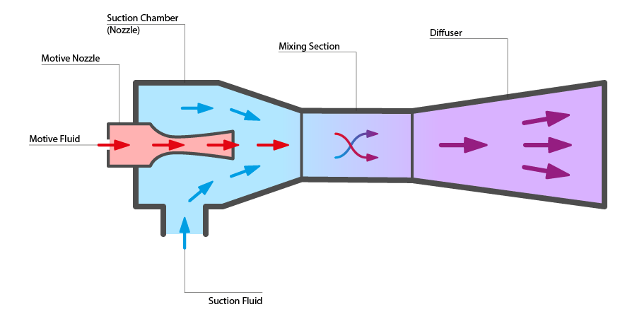
The considerable gain in terms of efficiency depends on three main factors:- the lift effect is obtained without any external power consumption;
- MT compressors can operate with a lower DP because their suction pressure is now the receiver pressure value and no longer the MT unit pressure;
- As MT suction is no longer the MT evaporator pressure, the MT unit superheat can be reduced, thus increasing the evaporator working pressure and consequently overall system efficiency.
Three valve configuration |
Parallel compression system |
Ejector system |
|
Three valve configuration |
|
Parallel compression system |
|
Ejector system |